In-place components are a great way to add custom uniquely designed elements to your design models. Through a series of solids and voids, they allow you to design unique forms that belong to quantifiable and parametrically similar categories. Here's the catch:
Don't use in-place components for any element that repeats more than once (maybe twice) in your model. For that, we'll be using component families that are modeled outside of the project environment. In-place components could be used for some millwork/casework, built-in furniture, reception desks, complex ceilings, etc.
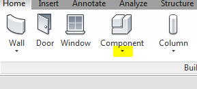
So here it goes! The "Model In-place" tool can be found under the component tool in the Build panel of the Home tab (1). After selecting this function, you'll be asked to choose a category for your in-place component (2). These categories make the component behave like other members of the group, for instance, if you choose "ceiling," the component will receive ceiling hosted lights. These categories will also allow you to schedule the components and control their visibility in the "VV" menu.
 |
| 1. Model In-place tool |
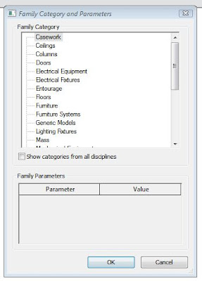 |
| 2. Choose the appropriate category for your model |
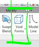
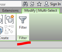
Activating the Model In-place tool changes the options available in the ribbon (3). Because you are now working in this in-place modeling environment, the functions you can perform differ from the typical project modeling workspace. Most notably, you'll be able to create forms with solids and voids.
Creating an extrusion activates "sketch mode" who's pink lines should be familiar to you now (4), having worked with floors and ceilings. Most of the Forms tools require a profile that is created in sketch mode and must be an outline that forms a closed loop (no gaps or overlapping lines).
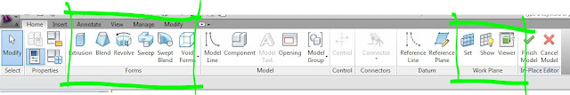 |
| 3. Model In-Place Ribbon - you'll be using the "forms" and "work place" tabs heavily |
Once you've created your profile outline, you click the green check mark on the ribbon.
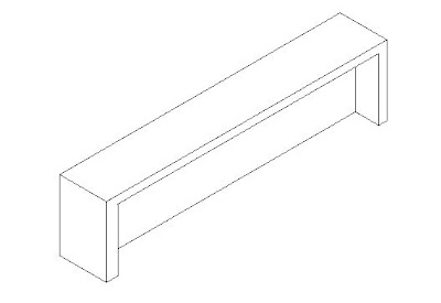
The depth of the extrusion is controlled by a field in the option bar. In this case I'm modeling a piece of millwork that may be used as a reception desk, so I'll change the depth from 1'-0" to 3'-0" (5). You can also change the depth of an extrusion from the properties menu, but instead of indicating "depth" you'll be indicating where the extrusion starts and finishes in relation to the plane on which you drew the profile.
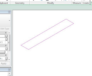 |
| 4. Drawing the extrusion profile in sketch mode. |
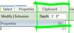 |
| 5. Depth can be changed in the options bar. |
Void forms can be used to add further dimension to your In-place model (6). You'll notice that you have the same options (extrusion, revolve, sweep, etc.) when working with voids as you do when working with solids. The combination of solids and voids offer endless opportunities for modeling.
 |
| 6. Add some voids |
In this example, I'm going to change the work plane from the floor level (which is the default) to the side of the desk to create an indentation. To do this I'll select the "Set" tool from the Work Plane panel (7). This activates a dialogue box (8) which asks how I'd like to choose my new work plane. In this case I am going to "Pick a Plane" which will be the easiest way for me to select the face of the desk.
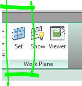 |
| 7. Set a new work plane |
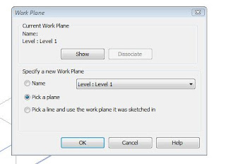 |
| 8. How do you want to set your plane? |
 |
| 9. Choosing the face of the desk as the work plane. |
 |
| 10. Drawing my profile directly onto the work plane |
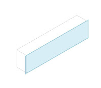
You are able to toggle the visibility of the active work plane with the "Show" tool also located in the Work Plane panel (7,9). With the work plane active on the face of the desk, select your extrusion tool and begin drawing the profile for the void extrusion (10).
Once complete, I set the depth of the void extrusion to 1' which provides a recessed area in the front of the desk (11).
 |
| 11. Void Extrusion with 1' depth. |
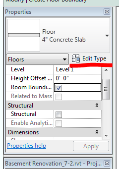
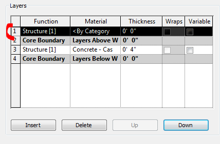
If you want to add materials to your model (14), you can select individual forms and change their materials in the properties window (12). Alternatively, you can paint materials onto forms by using the paint tool in the Geometry panel on the ribbon (13). Painting is a quick and dirty way to apply distinct materials to different faces of an object. When finished editing your model, you'll click on the green check (15) to close the "In-Place Editor"
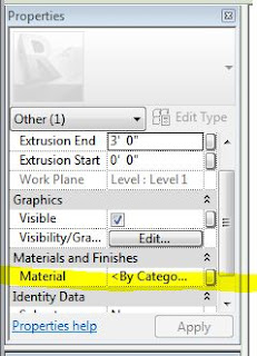 |
| 12. Adding materials to extrusions. |
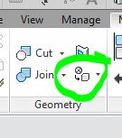 |
| 13. Paint tool |
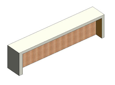 |
| 14. Desk with materials |
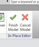 |
| 15. Finish it up! |
Your model will now show up in the Project Browser under the Families section (16). You can always return to the In-Place Editor to work on your model by selecting the model and then clicking "Edit In-Place" (17) on the contextual tab of the ribbon. Just remember, when you're editing the model, you'll also need to select and edit the individual extrusions located within.
In-place models will allow you to get some unique elements into your projects. Just remember to not copy them -- they are for one-of-a-kind elements. The skills you develop modeling these components will help you tremendously when we move into working with the Family Editor.
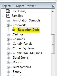 |
| 16. Project Browser |
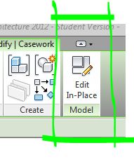 |
| 17. Edit in-place |


