Tuesday, March 5, 2013

Final Rendering Composition

DUE: Thursday, March 14th, 2:00 pm

Objective:

To explore ways of using Revit and other computer design software as a means of generating concept relevant visualizations.  The goal for this assignment is to create compelling and attractive renderings that showcase your skills as well as the project's aesthetic concept. 

Execution:

  1. View Composition: Evaluate your model and determine a perspective view that would best convey your design intentions. The view should be relatively wide, encompassing a large space.  If you wish, you can choose two narrower views.  You will be evaluated on your view composition, so spend some time and attention on the camera view, angle, cropping, depth of field, etc... make your adjustments intentional.
  2. Materials: Once you've determined which view(s) you would like to render, assign materials to the elements in the field of view.  You'll need to create bitmaps and bumps for custom materials.  If there are materials that you are using from the resource library, you should scan them as jpeg or png files.
  3. Lighting: Make sure that the natural and artificial light illuminating the area of your perspective is carefully considered.  You should plan for ambient light, task lighting, and any other effects you might want to achieve, using Light Groups for control. It is recommended that you choose a view which allows natural light penetration, and you should also consider the time of day and year in order to control shadows and exterior light quality. 
  4. Rendering:  Set-up and render your view per in-class discussions so that you have an appropriate resolution, size, and quality.
  5. Post-Processing:  After your rendering is complete from Revit, use Photoshop, Illustrator, manual techniques, or other tool(s) to add elements, a unique style to your image, as well as make any corrections and improvements to the rendered output.  This can include, but is not limited to, adding people, plants, exterior imagery, art, accessories, or adjusting color, light, etc. Your goal should be to not only depict the space in a reasonably accurate manner, but also convey the aesthetic concept of your design.  You will be evaluated on how successful you are in conveying a mood and style in your final rendering.  I recommend searching the internet, books, professional, and classmate work for rendering styles that you find particularly successful.  Remember, it is not necessary to produce the "slickest," most photo-realistic rendering for your project. 
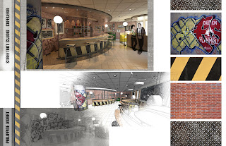
  6. Composition: Create a digital board for your project rendering that shows the raw rendering from Revit, your final post-processed rendering, and any materials or concept imagery that might support your visualization strategy.  You may want to include process work as well. Your name and the project name should be incorporated into the board.  Consider composition in your layout.  Size of the board is at your discretion.

Submission:

Submit your "board" as a pdf to your dropbox in a folder named "Final Rendering" by 2pm on Thursday, March 14th.  Failure to correctly submit your project will result in a deduction of 10 points.  Work submitted after 2:00pm will not be accepted and you will receive a grade of "0" for this assignment. 

Evaluation Criteria:

In addition to successfully completing the requirements of this assignment and your use of the technical tools at your disposal, you will also be evaluated on the following criteria:
  • How well does the rendering convey the project's big idea?
  • How is mood used to create a sense of the environment through lighting, texture, etc.?
  • How inventive is your final rendering style, and does it reflect a willingness to try new techniques?
  • Is the view composition carefully considered and used as a means of creating a mood and sense of the overall space?
  • Are the materials used unique to the project and successfully created to give a good tactile sense of the space?
Some past examples:


Tuesday, February 26, 2013

Stair Exercise

Objective:

To gain competency in using the stair tool as a means of communicating multiple styles of stairs in an interior design project.

Execution:

Design 3 unique stairs -- outside of a modeled building environment. The three must be different types (spiral, circular, switch-back, L-Shaped, U-Wide, etc.) and one must be a monumental stair.

Each stair must span a floor to floor height of 15 feet.

Landings must be included, where necessary, and stairs must meet code requirements.

Submission Requirements:

Each stair must be on its own 11x17 sheet with titleblock.  The 11x17 sheet must show the stair in a 3D axon, plan, and elevation view.  Scale will be determined by your individual stair and how it best fits on the sheet. View style for the 3D view is at your discretion, but the elevation and plan must use Hidden Line mode. 

Combine the 11x17 sheets into one single pdf and submit it to Blackboard by 5pm on Friday, March 1st.  No late work will be accepted, and incorrectly submitted assignments will receive an automatic deduction of 10 points.

It is in your best interest to do as much as you can with the stairs -- above and beyond assignment requirements.  

Check out this link from Autodesk University on improvements made to stairs and railings in Revit 2013.

Some Past Examples:

Thursday, February 21, 2013

Schematic Presentation Sheets

Extracting the "I" in BIM is one of the most important steps in the project delivery process. Tags, schedules, and legends allow us to use a BIM software like Revit to visualize the parametric information living within our projects. This information is represented both graphically and through text in construction documents, communicating how a building is to be delivered. In the context of this class and your relatively small projects, I want you to have experience of producing some documentation, without necessarily creating a full set of construction documents. This assignment is called "Schematic Presentation Sheets" but really it will be a small set of documents annotating your project.

Execution...


For this assignment you'll be creating a set of sheets with a custom titleblock for the following views:
  • cover sheet
    • name
    • project name
    • drawing index
    • include a 3D view 
    • include an image (optional) and title
  • demo plan (1/8" = 1'-0")
    • show walls to be demolished as dashed
    • provide critical dimensions
  • new construction plan (1/8" = 1'-0")
    • graphically differentiate between existing and new walls
    • no furniture -- only constructed elements
    • provide rooms tags with names and numbers
    • provide critical dimensions
    • provide door tags
    • coordinated with elevation symbol
  • furniture plan (1/8" = 1'-0")
    • grayscale walls and other items from new construction plan
    • tag all furniture
  • RCP (1/8" = 1'-0")
    • no dims necessary
    • ceiling tags
    • lighting fixture tags
  • 1 room color plan with legend (1/8"=1'-0")
  • 1 elevation (1/4" = 1'-0")
    • proper lineweights
    • detail lines for added information 
    • height dimensions
    • at least one hatch pattern
    • material callouts
    • detail section tag coordinated
  • 1 detail section (1-1/2" = 1'-0")
    • from element found on elevation
    • proper lineweights
    • detail lines for added information 
    • height dimensions
    • material callouts
    • at least one hatch pattern
  • 1 schedule of your choice
    • could be doors, furniture, lighting, etc. 

The above views must be placed on ARCH C (17" x 22") sheets with a customized titleblock.  The titleblock should not contain any blank fields, and needs to include your name, the project name, project address, and the date. 

Submission Requirements:


On Tuesday, March 5th you will submit a PDF PORTFOLIO of your sheets (arranged in order) to Blackboard by 2:00pm.  You will also bring to class a printed set of drawings scaled to 11x17 paper, stapled on the binding edge. Failure to have either of these submitted correctly by the start of class (2pm) on the 16th will result in a deduction of 10 points. Work will not be accepted after 2:15 pm and you will receive a grade of "0" for this assignment. 

Tuesday, February 12, 2013

Component Family Exercise

Project Description:

According to Autodesk, "A family is a group of elements with a common set of properties, called parameters, and a related graphic representation.  Different elements belonging to a family may have different values for some or all of their parameters, but the set of parameters (their names and meanings) is the same.  These variations within the family are called family types or [just] types."

The goal of this assignment is to develop a usable, parametrically flexible family that is an asset to current and future projects.

PART 1: Component Family Research

DUE: Tuesday, February 19th
Bring to class photos, measurements, and orthographic sketches (front elev, plan, side elevation, etc.) of an object that you would like to model as a component family.  This object must be something that can have multiple family types -- with at least one of the parameters being dimensional. If you are unsure, you may want to bring multiple choices.  You must have dimensions, photos, and sketches as these will be submitted in the final project.

When considering your object(s), you might want to pick something that is somewhat appropriate for your designed space, as you will be required to use the family in your model.  I will allow you to make some deviations from the selected object or custom design choices when creating your family as long as you provide hand sketches of what you want to create/change.

PART 2: Modeled Component Family

Your family must include the following:
  1. Material Parameter(s)
  2. Must include a nested family
  3. Must have at least 4 types that are "built-in" to the family
  4. Must flex and not fail!
On Tuesday, February 26th, you will submit the following to your class dropbox in a folder named "Component Family Exercsie":

  1. Your .rfa family file
  2. A pdf from your schematic design model showing how you used your family in your project
  3. Scans of your original object images and sketches (Part 1)
Files must be submitted by 2:00pm on the 26th.  No late work will be accepted. 


Family Tutorials:

Autodesk Family Tutorials
Lynda Comprehensive Family Tutorial (you may want to skip over the "tag" family section for now)

Thursday, February 7, 2013

Schematic Design Model

Now that we have  committed to our primary design option, and after creating a "save as" of our models, moved forward on the next assignment, the "Schematic Design Model."
The title of this phase is a bit of a misnomer since many of you already have models that are far beyond the "schematic" phase. To that end, I expect your models to include the following, by next Thursday (Feb 14):
  • accurate wall types with any sweeps and reveals
  • generic furniture that is in a similar size to what you will use for the final
  • ceilings with appropriate heights and materials
  • generic light fixtures 
  • floors with appropriate heights, designs, and finishes
  • interior glazing (including interior windows, curtain walls, etc.)
  • casework: you can use generic components or take a stab at modeling custom
  • any exterior fenestration changes
  • at least one in-place model
While I will not be grading  you on your designs per se, you should consider adding a level of complexity that shows your understanding of Revit.  For instance, designing a unique grid pattern in a curtain wall, creating multiple floor heights or ramps, designing a unique ceiling with varying levels and materials, creating custom wall sweep profiles, etc.

We will continue to work on your models in class on Tuesday, and you should come to class with any questions and challenges you might have. 

Submit your Revit file to the class Drop Box by 2:00pm on Thursday, February 14th.  Make a folder in your dropbox called, "Schematic Model," and place your file within.


Tuesday, February 5, 2013

Design Layout Options Assignment -- Final Phase

Hey guys!  Good work providing design options on trace as well as translating one of those options to a color area plan.

For the final portion of the Design Layout Options assignment, I will need you to upload your Revit files to the T:/ for review.  Your model should have accurate phasing with all of the previous as-built elements still intact.  I will also be looking for the following:

  • Three floor plan layout options utilizing 3 unique design options within one option set.
  • Your options should include walls, glass, doors, generic furniture, and floors.  You will also want to include changes to the exterior wall such as adding new entrances, windows, and porches. 
  • Three separate floor plan views with their visibility settings adjusted to show the corresponding design option.
    • Your floor plans should be named: "Level 1 - Option 1", "Level 1 -- Option 2", and "Level 1 -- Option 3"
Models will be placed in your T: drive. To do this, do a "save as" of the model and use the following naming convention:  DesignOptions_[your.last.name].rvt
Create a folder in the root of your T: drive for the file named: "Design Options"

Assignments must be submitted to the T: drive by 2:00pm on Thursday, February 7th. Incorrectly named or submitted files will result in a deduction of 5 points from this assignment's final grade.

Thursday, January 24, 2013

Design Layout Options Assignment

Assignment Overview:

Now that we have successfully completed our as-built drawings, and assigned appropriate phasing to our models and views, it is time to begin thinking about the design of the new space.  For this assignment you will be creating options for how your space may be laid out in floor plan.

Execution:

Print a 1/8"=1'-0" scale floor plan of the shell space to an 11x17 sheet of paper.
Using trace, develop 3 different potential layouts for the space, considering the different functions required by your "client."
Your trace drawings should show wall thickness and doors.  You will probably also want to show necessary furniture (eg. desks in offices, cash wraps, etc.)
Trace sketches should be neat -- I recommend tracing the building shell and then using grid paper under the trace to freehand your layout options.
Choose one layout that you think is most successful and interpret that design in Revit using an Area Plan.
Your Area plan must be in color and have an associated color legend.

Submission Requirements:

On Tuesday, January 29, you will present preliminary hand sketch layouts.

By 2pm on Tuesday, February 5th, you must submit, to Blackboard,a single pdf that contains 1 scan of each of the different trace layouts and a pdf print of your Revit color Area Plan and Legend to 1/8"=1'-0" scale.