Wednesday, August 15, 2012

Tags and Labels

In order to properly annotate your views in Revit, you will need to explore using tags.  Tags combine simple lines with a text Label to extract parametric information from a particular category of Revit component.  For example, I could instruct the tag's label to show the "Family Name" (an available parameter within the furniture family) for a particular piece of furniture. Anytime I place that tag on a piece of furniture in my model, it will display the family's name. If I change the family name, all of the tags will update.  See below:


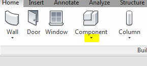
To create a custom tag you'll start by going to the Revit Application button and selecting New>Family.  From there, you'll choose your template.  In this case you'll want a family template from the annotations category.  For something like furniture, you'll want to use the "Generic Tag" template. 

This opens the template, allowing you to create your custom tag family.  Pay careful attention to the note found in the tag template:
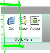
You change the family's category by using the Family Category and Parameters menu found on the Home Tab of the ribbon on the "Properties" Panel. 


My next step is to add my Label which is also found on the Home Tab. Make sure that you choose Label and not Text.  Text will allow you to add letter forms that do not react parametrically when tagging components.


After placing the Label in the family template, a menu will open asking you to select the parameter for which the label will display.  In this example, only parameters that are common to the Furniture family category are available to choose.  Select the parameter and then click the green arrow to assign it to your label. In this example, I'm going to choose type mark because I want to be able to show, on my furniture plans, the same information for each type of furniture specified. For something like door tags, I may want to display "Mark" since it is an instance parameter and will show a unique value for each door. 


Before leaving this menu, I'm also going to change the "sample value" to more accurately represent the type of tag I use for furniture (eg. Occasional Table = OT-01). By changing the sample value, I'll know where to place my lines so that my tag symbol is large enough to accommodate the text I want to display.


My Label now appears in the family, and I can add lines to form a border for the tag. 


Finally, load your family into your project and tag the furniture by visiting the Annotate tab on the Ribbon and choosing "Tag By Category."  As you hover over the furniture, your tag should appear and place itself when the mouse is clicked.
But, wait!  What's this? There is no information in my tag... or a blue "?" appears!


This simply means that there is no information for the parameter that the Label is pointing to.  If you'll recall, when setting up the furniture tag's label, we selected the "Type Mark" parameter for the furniture category of family.  Let's check out the Furniture family type that we are selecting and see what is going on.  Since it is called "Type Mark" I'm going to assume that this parameter is a Type parameter and not an instance parameter, so, with the piece of furniture in question selected, I'll click "Edit Type" from the properties menu to inspect. Sure enough, there is no data entered into the "Type Mark" identity data parameter. As soon as I place my desired furniture code into that field, I'll see my tags automatically populate. 


Remember, you can make tags that pull information from any category of family and any family parameter.  You can even have tags with multiple labels that display more than one parameter at a time (like a ceiling tag which displays the name of the ceiling as well as the height simultaneously).  Tags are a fantastic way to very quickly see the power of a parametric database and help in efficiently producing a well coordinate set of documents.

Monday, August 13, 2012

One Happy Family.

Hi guys.
Nice work on the Component Family Exercise.  Thought you might like to see what all of your families would look like if they all hung out together.


I also uploaded a Revit file, containing all off your families, if you would like to incorporate one of your classmate's families into your project.  The file can be downloaded here


Wednesday, August 1, 2012

Schematic Model Images

Here are some images from the models that were submitted on Tuesday.
Everyone is making great progress!

Art Studio and Bar

Art Studio and Bar

Baby Food Store

Candy Shop & Kitchen

Ceramics Studio with Custom Kilns

Fashion Design Studio

Fashion Design Studio with Crazy Corridor Ceiling!

Phasing and Visibility -- Revisited

A few of you had mentioned that the glass in your exterior walls was showing up as opaque (gray) in 3D views.  Those walls and their windows should have been set to the existing phase.  In your 3D views, the way we currently have the Phase Filters set-up (Show Previous + New - fig 1) is creating a graphic override for any element on the existing phase to make it appear gray (fig 2).  This allows us to quickly identify what is existing and what is new. If we want the existing elements to visually appear similar to the new construction elements in 3D views, we must change the Phase Filter in the view properties to "Show Complete" (fig 3).  This provides a visual representation of how the building will look when it is finished (fig 4).  The trick here is that if you work with this Phase Filter active it is difficult to graphically distinguish what is existing and what is new.  Be careful so that you are not deleting existing elements instead of demolishing them.
figure 1
figure 2
figure 3
figure 4


Tuesday, July 24, 2012

Model In-Place

In-place components are a great way to add custom uniquely designed elements to your design models.  Through a series of solids and voids, they allow you to design unique forms that belong to quantifiable and parametrically similar categories.  Here's the catch: Don't use in-place components for any element that repeats more than once (maybe twice) in your model. For that, we'll be using component families that are modeled outside of the project environment. In-place components could be used for some millwork/casework, built-in furniture, reception desks, complex ceilings, etc. 

So here it goes!  The "Model In-place" tool can be found under the component tool in the Build panel of the Home tab (1).  After selecting this function, you'll be asked to choose a category for your in-place component (2). These categories make the component behave like other members of the group, for instance, if you choose "ceiling," the component will receive ceiling hosted lights.  These categories will also allow you to schedule the components and control their visibility in the "VV" menu.
1. Model In-place tool
2. Choose the appropriate category for your model
Activating the Model In-place tool changes the options available in the ribbon (3).  Because you are now working in this in-place modeling environment, the functions you can perform differ from the typical project modeling workspace. Most notably, you'll be able to create forms with solids and voids.
Creating an extrusion activates "sketch mode" who's pink lines should be familiar to you now (4), having worked with floors and ceilings. Most of the Forms tools require a profile that is created in sketch mode and must be an outline that forms a closed loop (no gaps or overlapping lines).
3. Model In-Place Ribbon - you'll be using the "forms" and "work place" tabs heavily
Once you've created your profile outline, you click the green check mark on the ribbon.

The depth of the extrusion is controlled by a field in the option bar.  In this case I'm modeling a piece of millwork that may be used as a reception desk, so I'll change the depth from 1'-0" to 3'-0" (5). You can also change the depth of an extrusion from the properties menu, but instead of indicating "depth" you'll be indicating where the extrusion starts and finishes in relation to the plane on which you drew the profile.

4. Drawing the extrusion profile in sketch mode.
5. Depth can be changed in the options bar.


 Void forms can be used to add further dimension to your In-place model (6).  You'll notice that you have the same options (extrusion, revolve, sweep, etc.) when working with voids as you do when working with solids.  The combination of solids and voids offer endless opportunities for modeling.
6. Add some voids

 In this example, I'm going to change the work plane from the floor level (which is the default) to the side of the desk to create an indentation. To do this I'll select the "Set" tool from the Work Plane panel (7).  This activates a dialogue box (8) which asks how I'd like to choose my new work plane.  In this case I am going to "Pick a Plane" which will be the easiest way for me to select the face of the desk. 
7. Set a new work plane

8. How do you want to set your plane?

9. Choosing the face of the desk as the work plane.

10. Drawing my profile directly onto the work plane


You are able to toggle the visibility of the active work plane with the "Show" tool also located in the Work Plane panel (7,9). With the work plane active on the face of the desk, select your extrusion tool and begin drawing the profile for the void extrusion (10).
Once complete, I set the depth of the void extrusion to 1' which provides a recessed area in the front of the desk (11). 
11. Void Extrusion with 1' depth.
If you want to add materials to your model (14), you can select individual forms and change their materials in the properties window (12).  Alternatively, you can paint materials onto forms by using the paint tool in the Geometry panel on the ribbon (13). Painting is a quick and dirty way to apply distinct materials to different faces of an object.  When finished editing your model, you'll click on the green check (15) to close the "In-Place Editor"
12. Adding materials to extrusions.
13. Paint tool


14. Desk with materials

15. Finish it up!

Your model will now show up in the Project Browser under the Families section (16). You can always return to the In-Place Editor to work on your model by selecting the model and then clicking "Edit In-Place" (17) on the contextual tab of the ribbon. Just remember, when you're editing the model, you'll also need to select and edit the individual extrusions located within.
In-place models will allow you to get some unique elements into your projects.  Just remember to not copy them -- they are for one-of-a-kind elements. The skills you develop modeling these components will help you tremendously when we move into working with the Family Editor.

16. Project Browser
17. Edit in-place

Friday, July 20, 2012

Design Options Tutorial

Here is a link to a post on the "Revit Zone" blog about design options.  Check it out if you need a refresher on the in-class demos.  I'll try and add some of my own steps, reminders, and screenshots in the near future.

Revit Zone Design Options

Tuesday, July 17, 2012

Phase Settings for Views

As requested, below are posted screen shots of the proper phase and phase filter settings for the Existing, Demo, and New Construction Floor plans you are required to create.  If you have all of the modeled elements set to the correct phase, then their graphic display properties should adjust correctly for the different plans using these settings.

1) Existing Plan -- in this view you want to see all of the existing modeled elements before any demo or new construction.


2) Demo Plan -- in this view we want to be able to tell the difference between what existing elements will stay and what will be demolished in the renovation.  Demolished elements should appear as dashed. 


 3) New Construction Plan -- this is what will become our working view for all new elements of the renovation, and may eventually end up on a sheet to be issued to the contractor. The demolished walls are no longer visible, but the existing walls to remain still appear. As we draw our new elements on this plan they will be created in the "New Construction" phase. 


Printing to 11x17

Here are screen shots of how I recommend setting your printing options to generate 11x17 prints to the classroom laser printer.

The print command can be found under the application button or by pressing CTRL+P.

1) Make sure that the correct printer is selected at the top of the print menu and then click "Settings" at the bottom right of the menu to determine the characteristics for your print.


2) Adjust the print setup menu to the options indicated in the screenshot below. Pay particular attention to the zoom option.  By clicking "Zoom: 100%" you are indicating that you want your drawing printed to the same scale that is indicated by the view which is being printed. If you select "Fit to Page," the printer will shrink or expand the view to fill the paper, creating a drawing that may or may not be easily measured with a scale ruler. 
Also, note the option to hide unreferenced view tags which prevents printing of miscellaneous view tags for temporary or working views that have yet to make it onto sheets.

Revit Print Setup

3) By clicking OK (you can save this print setting for a later point if you'd like) you will return to the print menu and can select the "Print Range" at the bottom left corner.  By selecting "current window," the entire extents of the view will be printed which includes any distant elevation tags or grids which extend far beyond the model itself.   This is important to consider, because if your view does not fit on the 11x17 sheet, you may need to adjust your visibility settings to crop or hide elements that make it too large for the paper size.

Revit Print Range

Note: To create a pdf, simply change the printer at the top of the print menu to "Adobe PDF."  If working from home, and you do not have Adobe Acrobat installed, you may have trouble creating pdfs from Revit.  When you are using the Adobe PDF printer, make sure you check the properties to ensure that the settings match your desired print output.

Revit Print Properties